Product & Service

Home/Product & Service
  • Application
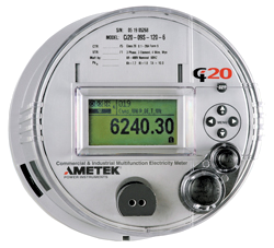
    • AMETEK’s Ci20 Revenue Meter watches over your energy investment in many ways.
    • It has high accuracy measurements, site diagnostics and dependable communication options to ensure maximum reliability
    • Your installation investment is reduced with our innovative software wizard that provides quick set-up and configuration.
    • Inventory and ordering is simplified with field upgradeable options using soft switches and plug in boards.
    Specifications METER FORMS Meter Forms: 5, 6, 8, 9, 26, 35S, Universal INPUTS Voltage
    • 55-530 VAC auto-ranging
    • Burden*: 0.5 VA @ 530V *Does not include auxiliary power requirements.
    Current
    • 10 Amps: ANSI Class 20
    • Burden: 0.5 VA maximum
    • Overload: 1.5x rated class current continuous, 20x rated class current for 0.50 sec
    • Frequency range: 45-55 Hz, 55-65 Hz
    AUXILIARY POWER 55 – 530 VAC
    • Derived from from A,B or C phase voltage input Auxiliary Power Burden
    • 15 VA maximum
    ACCURACY Watthour
    • 0.15% reading Clock
    • Synchronized to line
    LOAD PROFILE
    • 4 Channels of Storage (Standard) Programmable Interval
    • 1-60 minutes 64 Days Storage Using Four Channels at 15-minute Intervals
    Details
  • Application
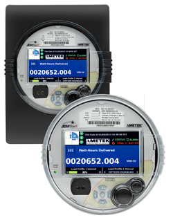
    • AMETEK’s JEMStar II has the highest accuracy in the market.
    • Provides many communication options and monitors your power quality to make it the ideal choice for any metering application.
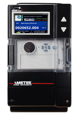
    • An impressive color display makes it easy to view power measurements, phasor displays and meter diagnostics.
    • The JEMStar II is easy to use and configure with our intuitive JEMWARE software and the meter display provides a user menu to show and edit configuration details.
    • The JEMStar II has a GB of non-volatile memory to store your metering and power quality data for as long as you want.
    • The meter has a single base model that can be used for simple revenue and billing applications as well as more complex power quality monitoring applications.
    Specifications METER FORMS
    • Meter Forms: 5, 6, 8, 9, 45, Universal
    INPUTS Voltage
    • 55-530 VAC auto-ranging
    • Burden*: 0.5 VA @ 530V * Does not include auxiliary power requirements.
    Current
    • 1 amp: ANSI class 2
    • 5 amps: ANSI class 10
    • 10 amps: ANSI class 20
    • Burden: 0.5 VA maximum
    • Overload: 1.5x rated class current continuous
    • Starting current: 0.002 A
    • Frequency range: 45-55 Hz, 55-65 Hz
    AUXILIARY POWER S-base and A-base
    • Self powered via all three phases: 55-530 VAC
    • External Aux Power Option: 55-530 VAC or 90-300 VDC; 19-58 VDC
    Swichboard
    • Aux Power: 55-530 VAC or 90-300 VDC; 19-58 VDC option
    Auxiliary Power Burden
    • 25 VA maximum
    ACCURACY Watt Hour
    • 0.05% reading (0.02% typical) Volts, Amps
    • 0.04% reading
    LOAD PROFILE
    • 16 channels storage
    • 1-60 minute intervals
    TIME SYNC
    • Internal clock: 0.5 sec/day accuracy
    • 50/60HZ line frequency
    • External time sync options: IRIG-B, NTP, IEEE-1588, PPS
    Details
  • Application
    • AMETEK’s JEMStar II has the highest accuracy in the market.
    • Provides many communication options and monitors your power quality to make it the ideal choice for any metering application.
    • An impressive color display makes it easy to view power measurements, phasor displays and meter diagnostics.
    • The JEMStar II is easy to use and configure with our intuitive JEMWARE software and the meter display provides a user menu to show and edit configuration details.
    • The JEMStar II has a GB of non-volatile memory to store your metering and power quality data for as long as you want.
    • The meter has a single base model that can be used for simple revenue and billing applications as well as more complex power quality monitoring applications.
    Specifications METER FORMS
    • Meter Forms: 5, 6, 8, 9, 45, Universal
    INPUTS Voltage
    • 55-300 VAC auto-ranging
    • Burden*: 0.5 VA @ 300V * Does not include auxiliary power requirements.
    Current
    • 1 amp: ANSI class 2
    • 5 amps: ANSI class 10
    • 10 amps: ANSI class 20
    • Burden: 0.5 VA maximum
    • Overload: 1.5x rated class current continuous
    • Starting current: 0.002 A
    • Frequency range: 45-55 Hz, 55-65 Hz
    AUXILIARY POWER Swichboard
    • Aux Power: 55-300 VAC or 90-300 VDC Auxiliary Power Burden
    • 25 VA maximum
    ACCURACY Watt Hour
    • 0.05% reading (0.02% typical) Volts, Amps
    • 0.04% reading
    LOAD PROFILE
    • 16 channels storage
    • 1-60 minute intervals
    TIME SYNC
    • Internal clock: 0.5 sec/day accuracy
    • 50/60HZ line frequency
    • External time sync options: NTP
    Details
  • Application
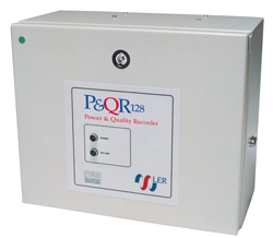
    • Power quality monitor--measures voltage and frequency profiles, voltage dips and surges, loss or supply, harmonic content, flicker, voltage and current imbalance
    • Transient fault recorder--analog inputs are sampled at up to 128 samples per cycle with a maximum record length of 2 seconds
    • Disturbance Recorder/Logger--analog inputs are sampled at up to 2 samples per cycle with RMS measurements recorded up to one minute
    • Trend Recording--input and computed quantities are logged as maximum, minimum and average quantities every minute for up to 16 weeks.
    • Remote Capabilities-via Ethernet or modem, and the process can be automated using the record's Auto-Call or Auto-Poll features.
    • Software--wide range of application software for communicating, configuring, downloading, displaying and analyzing recorded data. Auto-poll/Call automates the complete process of retrieving your recorded data.
    Specifications INPUTS Number of channels
    • 8 (4 voltage, 4 current) consult factory for other configurations Voltage Inputs
    • 150/300/600 RMS maximum, Star (wye) or delta connections Current Inputs
    • 1/5/100/200/500/1000 A RMS nominal thru external CTs. designed to record to 40% over-range Frequency Response
    • 40Hz-3kHz. (+0dB, -3dB for voltages) DC-3kHz (+0dB for currents) Accuracy
    • Better than 0.2% of full scale
    REAL TIME CLOCK Clock Source
    • 32,768 Hz internal crystal oscillator
    Resolution
    • 1 ms
    Range
    • Time and date (including leap year and day of the year) Synchronization
    • 50/60 Hz from voltage input
    ENCLOSURE Mounting
    • Wall (internal terminals) — 11.75 in. x 16.0 in. x 8.25 in. (300 mm x 400 mm x 210 mm)
    • 19" Rack Mounting — 13.25 in. x 19.0 in. x 5.25 in. (336 mm x 482 mm x 133 mm)
    • Portable — 14.25 in. x 13.75 in. x 5.25 in. (362 mm x 349 mm x 133 mm) Weight
    • 13.2-17.6 lbs. (6-8 kg) depending on enclosure style
    CERTIFICATION CE
    Details
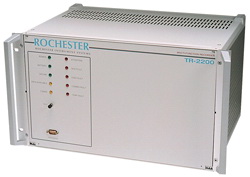
  • Application The Fault Recorder product family is enhanced with our full suite of software applications designed to simplify the process of configuring our recorders, retrieving event information, and analyzing the results. Tools like our automated event retrieval and expert analysis provide the quickest results when classifying an abnormal event. Detailed fault analysis is easily accomplished with our set of power analysis tools and flexible display options.
    Details
  • Application
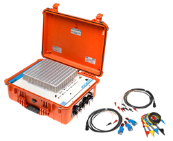
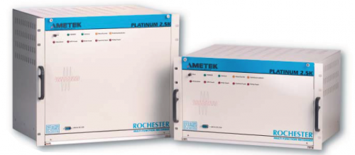
    • The Platinum 2.5K Portable Multi-Function Recorder is packaged in a rugged case with quick connect interfaces for fast and simple field connection.
    • Interface cables are provided with shrouded banana jacks that couple easily with a variety of measurement CT’s and voltage scaling devices offering complete flexibility for power utility and industrial use.
    • High-speed sinusoid data for traditional fault recorder analysis
    • Slower speed data for disturbance or swing recording
    • Continuous logging of RMS and phasor data for disturbance monitoring
    • Steady-state logging of RMS and harmonic spectrum values
    • System frequency for power quality analysis
    Inputs
    • Number of Channels 8 analog and 16 digital Voltage Inputs
    • 63.5 or 110 V RMS nominal
    • 480 or 600V RMS nominal (via external box) Current Inputs
    • 1 A or 5 A RMS nominal (thru current transformers, other ranges available) Frequency Response
    • DC – 1/2 sampling rate (1/4 sampling rate for 384 samples per cycle only) Accuracy
    • Better than 0.1% of full scale Digital Inputs
    • 24/48/125/250 VDC normally open or closed wetted contact
    SYSTEM TIMING Time Source
    • Optional internal GPS receiver with 1 PPS output for phasor measurement Accuracy
    • Normally better than +/- 60 ns
    ENCLOSURE Case and Unit
    • 30 lbs. (DIM)
    Details
  • Application
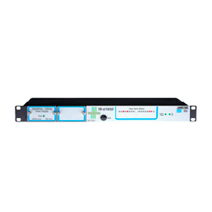
    • AMETEK’s TR61850 adds the capability to easily monitor and record GOOSE messages within the substation.
    • TR61850 automatically merge providing a single point of reference when analyzing transient events and system disturbances.
    • AMETEK’s TR61850 has IEC 61850-8 protocol for GOOSE messaging and supports subscription to 128 GOOSE messages from multiple IED’s within the substation.
    • TR61850 can be used with multiple transient fault recorders to provide a single complete record for all substation events.
    Specifications
    • Input Capacity 128 GOOSE Message subscriptions - GOOSE Messages are mapped virtual inputs - Supports mapping to multiple IED’s - 6 Hardwired digital inputs
    • Field Contacts - NO/NC software programmable - Programmable debounce or filter timers - 20-150 VDC FCV
    • Outputs - 8 form C (SPDT) relays, configurable functions: - Cross-Trigger, Watchdog, Loss of LAN1/2… - Energized or de-energized operation - Published GOOSE Messages - Status of 128 virtual inputs - Status of 8 contact outputs - Status of 16 hardwired inputs
    Time Stamping
    • 1 msec time stamp resolution
    • GOOSE Messages can be time stamped internally or by the GOOSE time stamp Time Synchronization
    • IRIG-B input (modulated or demodulated)
    • NTP time sync (can sync with up to 3 servers)
    • IEEE1588
    • Master/Slave sync with other TR61850 units via RS485
    • Slave sync with TR2000/TR2500 fault recorders with internal GPS via RS485 and fiber optic PPS
    Certifications
    • KEMA IEC61850 Compliance
    Details
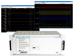
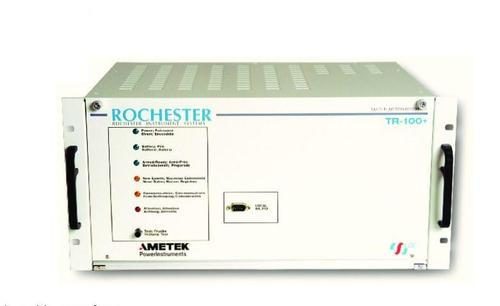
  • Application The AMETEK TR-100+ is a fully featured Digital Fault Recorder with the capability to capture and analyze short transient events, longer-term disturbances and trend input quantities such as RMS, frequency, harmonics, power and power factor. Specifications INPUTS Number of Channels • 8, 16, 24, or 32 analog
    • 16, 32, 48, or 64 digital (larger systems available) Voltage Inputs
    • 57 to120 V RMS nominal, 212 V RMS full scale Current Inputs
    • 1 A or 5 A RMS nominal (thru external current shunts/CICT’s) Frequency Response • DC to 3,000 Hz, (+0dB, -3dB) or 1/4 sample rate Accuracy
    • Better than 0.2% full scale Digital Inputs • 24-250 VDC normally open or normally closed wetted contact
    SYSTEM TIMING Time Synchronization
    • Internal clock, synched to the 50/60 Hz line or optional IRIG-B
    Details
  • Application
    • The Platinum 2.5K Portable Multi-Function Recorder is packaged in a rugged case with quick connect interfaces for fast and simple field connection.
    • Interface cables are provided with shrouded banana jacks that couple easily with a variety of measurement CT’s and voltage scaling devices offering complete flexibility for power utility and industrial use.
    • High-speed sinusoid data for traditional fault recorder analysis
    • Slower speed data for disturbance or swing recording
    • Continuous logging of RMS and phasor data for disturbance monitoring
    • Steady-state logging of RMS and harmonic spectrum values
    • System frequency for power quality analysis
    Inputs Number of Channels
    • 8 analog and 16 digital Voltage Inputs
    • 63.5 or 110 V RMS nominal
    • 480 or 600V RMS nominal (via external box) Current Inputs
    • 1 A or 5 A RMS nominal (thru current transformers, other ranges available) Frequency Response
    • DC – 1/2 sampling rate (1/4 sampling rate for 384 samples per cycle only) Accuracy
    • Better than 0.1% of full scale Digital Inputs
    • 24/48/125/250 VDC normally open or closed wetted contact
    SYSTEM TIMING Time Source
    • Optional internal GPS receiver with 1 PPS output for phasor measurement Accuracy
    • Normally better than +/- 60 ns
    ENCLOSURE Case and Unit
    • 30 lbs. (DIM)
    Details
  • Application
    • Fault and Disturbance Recorder
    • Transient Fault Location
    • Phasor Measurement Unit
    • Power Quality Monitor
    • Sequence of Events Recorder
    Specifications INPUTS Analog Inputs
    • Built in DSP for computations
    • 16 bits, 32768 levels (15 plus sign)
    • Fixed 512 samples/cycle (26KHz/31KHz)
    • Accuracy better than 0.1% of reading down to 3% of full scale Voltage Input Ranges
    • 1.414, 10, 150, 300V RMS full-scale or custom range (AC or DC compatible) Current Input Ranges
    • 1 A or 5 A RMS nominal (thru current shunts/CICT’s) Frequency Response
    • DC-1/2 sampling rate Digital Inputs
    • 24 to 250 VDC normally open or closed wetted contact Input Module
    • 6 analog (current or voltage) and 12 digital Inputs System Capacity (1-6 Input Modules)
    • 6, 12, 18, 24, 30 or 36 analog
    • 12, 24, 36, 48, 60 or 72 digital (multiple units tied together for larger systems)
    SYSTEM TIMING Time Synchronization Accuracy
    • 1 usec. or better
    • Internal GPS receiver
    • IRIG-B (Mod & TTL)
    • Network Time Protocol (NTP)
    ENCLOSURE Chassis
    • 4U (7”) 19” chassis mount
    CERTIFICATIONS CE  
    Details
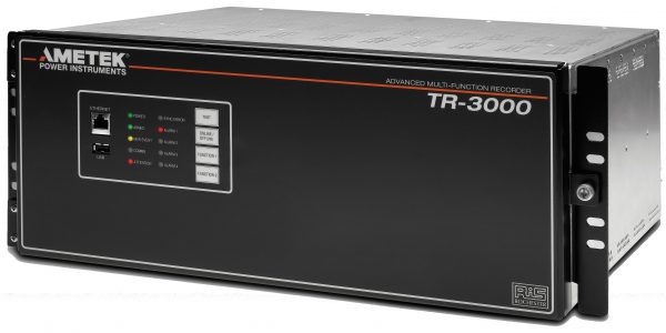
  • Application • For all types of power system events • Simultaneously perform: transient recording, disturbance recording, phasor measurements, power quality analysis, and sequence of events recording. • The system can operate automatically to retrieve events and perform an expert analysis so you have the answers fast, saving time and money. • Providing all the answers in one software platform. • The TR-2000 is ideally suited for your generation, transmission, and distribution power system monitoring.
    Details
  • Features L&T Valves launches a smart flow-control solution that enhances plant safety and reliability - L&T Valves Asset Management Program, LAMP. This IoT-ready remote valve performance monitoring system leverages expertise in valve manufacture as well as system design and integration. At the core of LAMP is a time-tested SIL3-capable valve - Ball, Butterfly, DBB Plug, Gate or Globe. Each valve is equipped with ValvTrac™ digital traceability tag that cross-links valve signature to traceability information such as valve test certificates, material test certificates, and installation, operation and maintenance manuals. The valves are upgraded to ‘Smart Valves’ by integrating them with next-generation smart sensors that measure parameters such as torque, leakage, vibration, pressure, temperature and position. The data is relayed real-time to a secure, dedicated cloud computing platform where it is analyzed to provide complete valve health and diagnostic information. Valve users can access information through a secure login, or port the data to the native asset management system through any standard field communication protocol (HART, WirelessHART, Foundation Fieldbus, etc.). To a customer, knowledge is trust; the more he knows about the state of a valve, the more confident can he be about its performance. Thus LAMP takes the guesswork out of valve maintenance and allows customers to transition from preventive maintenance based on thumb rules to predictive maintenance based on real data.
    Details
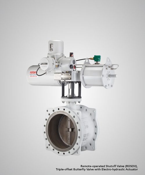
  • Automation Solutions Leveraging flow-control expertise that spans five decades and in-house capabilities in system design and integration, L&T Valves offers a comprehensive range of SIL-capable Valve Automation Solutions to meet myriad industry/ process/ customer requirements. Special Features & Benefits Product Range: High Integrity Pressure Protection Systems (HIPPS) Emergency Shut Down Valves (ESDV) Shut Down Valves (SDV) Remote Operated Shutoff Valves (ROSOV) Blowdown Valves (BDV) On/ Off Valves Remote Operated Valves/ Motor-operated Valves  
    Details
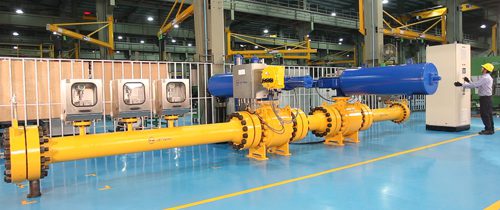
  • High Integrity Pressure Protection System L&T Valves offers a range of customised SIL3-capable High Integrity Pressure Protection Systems (HIPPS) for over-pressure protection In industrial plants, in case of over-pressurisation, the gases released are primarily flared. Flaring and venting of flammable gases pose health and safety hazards and constitute a significant threat to the environment.
    Details
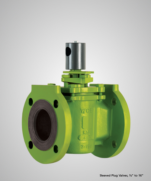
  • Special Features & Benefits Taper Plug Design - Lower operating torque compared to lubricated plug valves Plug Adjustment Option - Enables on-line maintenance Avoids downtime Large PTFE Sleeve - Bubble-tight shutoff No metal-to-metal contact Longer service life Positively-locked Sleeve - Reliable sealing through thermal cycles Wiping action between sleeve and plug - Durability in slurry lines Reverse-lip PFA Diaphragm - Self-adjusting dynamic stem seal provides assured sealing to atmosphere Rugged Body - Long and reliable service life No Cavities - Line Fluid does not get entrapped      
    Details
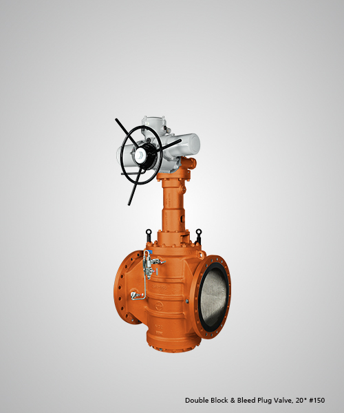
  • Special Features & Benefits Design complies to API 6D Valves offered with API 6D monogram Fugitive emissions – Complies to ISO 15848-1 Fire safety - Complies to API 607/ ISO 10497 CE Marking - Meets requirements of Pressure Equipment Directive 2014/68/EU, Annexure III, Module H PED Module B1 Design examination certificate (certified by DNV) available Atex - Meets requirements of Atex Directive 94/9/EC (ATEX), category 2 non-electrical equipment SIL3 - Safety Integrity Level SIL3 certification complies to IEC 61508 L&T Valves Double Block & Bleed Plug Valve provides online-verifiable bubble tight sealing and is a safe and reliable replacement to the conventional two-valve system High integrity positive shut-off obtained independent of line pressure, without sealants/ lubricants Mechanical sealing ensuring online-verifiable positive double isolation for critical services Patented operator mechanism enables segments to move towards the seats during valve operation – reduces wear and tear and enhances service life Inbuilt cavity pressure relief system Inline Maintainable Seats -Seats can be renewed without removing the valve from the pipeline (after draining and isolating the line)
    Details
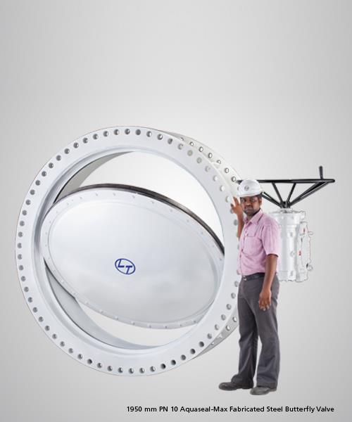
  • Aquaseal Max is a fabricated steel butterfly valve developed as an alternate for cast iron butterfly and sluice valves in water distribution systems. The highly reliable valve also finds application in power plants, utility and fire water lines, and HVAC systems. Customised Aquaseal Max can be used to handle air, gases and vacuum services. The valve has successfully under gone Proof of Design (POD) test as per AWWA C 504 and AWWA C 516. The key feature of Aquaseal Max Fabricated Steel Butterfly Valve is a Self-energising Disc Seal that uses line pressure to provide assured sealing. Special Features & Benefits Self-energising Disc Seal - Bi-directional bubble-tight sealing Assured Sealing to Atmosphere Lighter and Stronger Construction Lower Torque, Longer Life Maintenance-free Bearings  
    Details
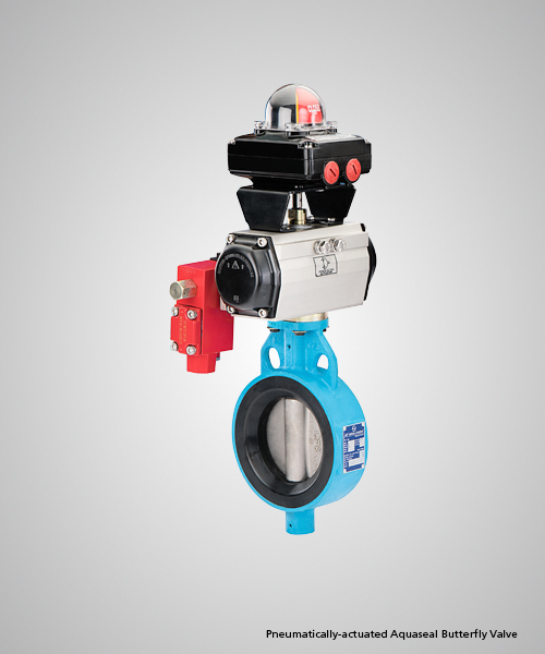
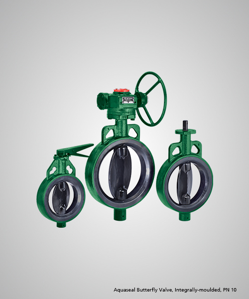
  • Special Features & Benefits Enhanced reliability, Longer service life Tight sealing, Consistent low torque Assured shaft sealing One-piece blowout-proof Shaft Reliable Drive - Positive shaft-disc connection Lower resistance to flow - Contoured disc Ease of installation Integral actuator mounting platform  
    Details
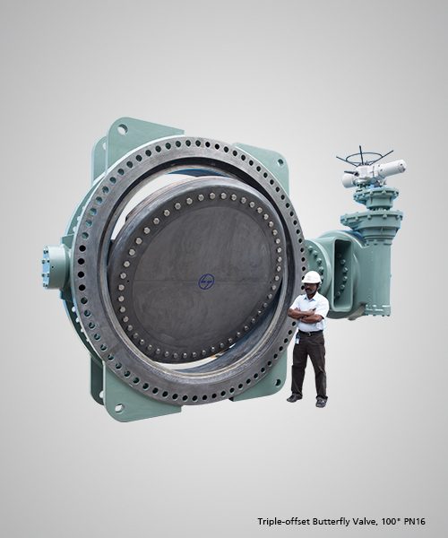
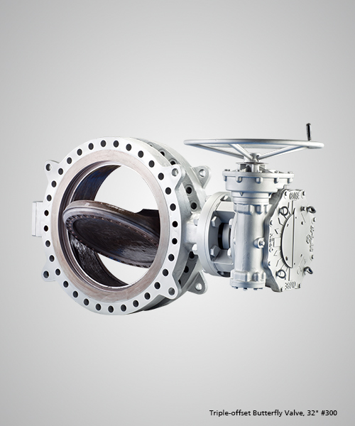
  • Special Features & Benefits Design complies to API 609 Valves offered with API 609 monogram Wide portfolio of Short-pattern and Long-pattern valves Design Validation Test - 12” Class 150 valve successfully completed 10,000 cycles Fugitive emissions - Complies to ISO 15848-1 Endurance Class CO2 and Tightness class AH Fire safe by design and complies to API 607/ ISO 10497 (preferred and non-preferred direction) API RP 591 test conducted on 12” Class 150 TOBV at Element Lab, USA CE Marking - Meets requirements of Pressure Equipment Directive 2014/68/EU, Annexure III, Module H PED Module B1 Design examination certificate (certified by DNV) available Atex - Meets requirements of Atex Directive 94/9/EC (ATEX), category 2 non-electrical equipment SIL3 Safety Integrity Level to IEC 61508 Triple-offset Geometry minimises seat-seal contact – lower operating torque and cost of ownership Compact and light weight as compared to gate valves of the same size Hard faced in-situ body seat and flexible laminar seal ensure bubble tight sealing Single piece Anti blow out shaft Disc contour ensures mimimum turbulence and pressure drop Retainer bolting complies to ASME Section VIII Div 1 Appendix 2    
    Details
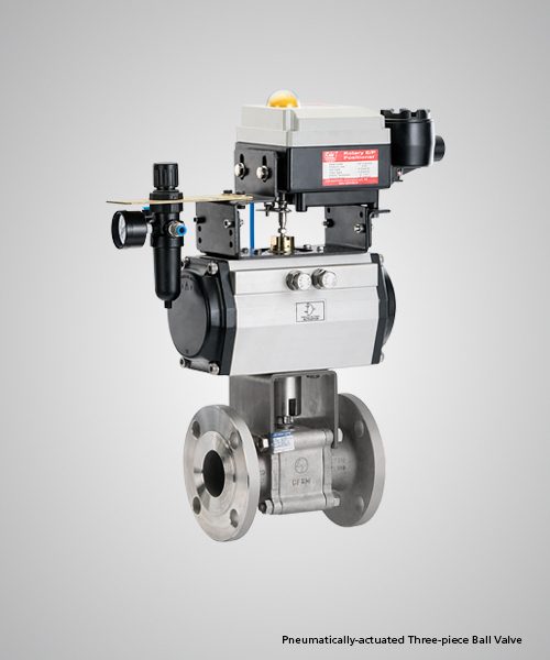
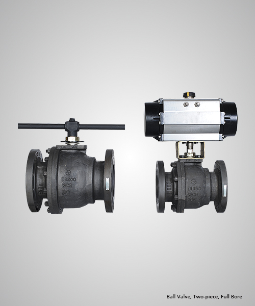
  • Features Floating Ball Valves Size 1/2" to 8" | ASME Class Class 150 to 2500 ISO 17292 | API 6D | API 608 1 Piece / 2 Piece / 3 Piece Construction Full / Reduced bore Soft Seat & Metal seat | Flanged-Screwed-Socket weld
    • Mirror-finished solid stainless ball
    • Fine-grained PTFE seats with Cavity Pressure Relief mechanism
    • Blowout-proof stem & Antistatic feature
    • High integrity stem sealing – Belleville springs compensate for wear and thermal expansions
    • Actuator-mounting flange conforms to ISO 5211
    Material of Constructions Carbon Steel, Stainless Steel, Duplex Stainless Steel, Inconel, Hastalloy, Monel
    Details
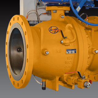
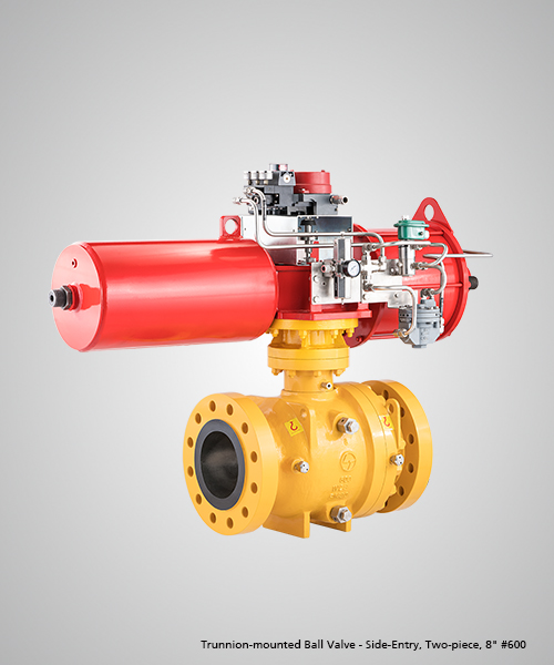
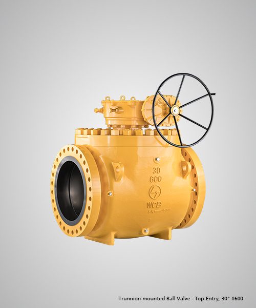
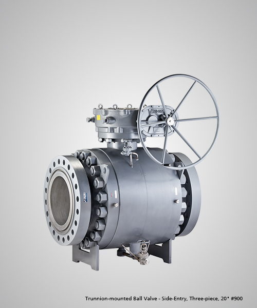
  • L&T Valves Limited Trunnion Mounted Ball Valves are of 2-piece / 3-piece design, with flanged or butt-weld ends. As a standard, the valves are manufactured in bolted body designs, where the joint between the body and the connector is bolted. The bolted body design offers flexibility for dismantling during field service in case of an emergency. Welded body designs, where the joint between the body and connector is welded, are also available on request Features Trunnion-mounted Ball Valves Size 2" to 56" | ASME Class Class 150 to 2500 API 6D | API 608 2 Piece/3 Piece Construction | Full/Reduced bore Side Entry & Top Entry | Soft Seat & Metal seat Bolted & Welded | Flanged & Buttweld Design
    • Trunnion-mounted Ball Valve design complies to API 6D and can be offered with API 6D monogram
    • Wide range of product portfolio in Side-entry and Top-entry designs
    • Valves successfully tested to Shell Design Evaluation Test, Procedure 77/300 for temperature -29 to 150 degree C (O rings) and -50 to 150 degree C (Lip seals)
    • Vaves for gas services can be supplied with High pressure gas test (Sniffing & Immersion Method)
    • Coil springs used for consistent seat loading and lower operating torque
    • Double block and bleed (DBB) feature - Valves are designed and tested for automatic cavity relief
    • Lip seals are provided for low temperature services & Cryogenic services
    • 2/3 stage Stem and 2 stage Body Joint sealing system; Primary O ring and Secondary graphite (in 3 stage stem, thrust washer is primary)
    • Where tight shut off is required, Double piston effect (DPE) seats provided for redundancy in sealing
    Details
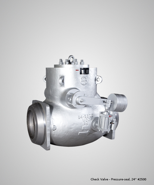
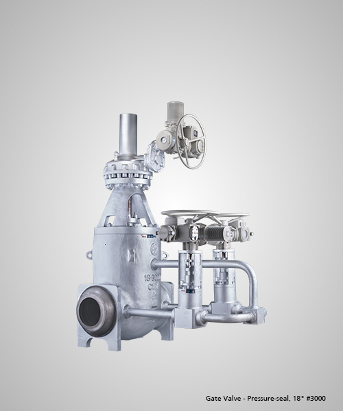
  • Special Features & Benefits Pressure-seal Check Valve conforms to ASME B 16.34. CE Marking - Meets requirements of Pressure Equipment Directive 2014/68/EU, Annexure III, Module H Atex - Meets requirements of Atex Directive 94/9/EC (ATEX), category 2 non-electrical equipment Safety Integrity Level for Automated Valves - SIL 3 certification available Valves in intermediate reduce cost of ownership Pressure-Seal mechanism utilizes line pressure to enhance seal; ensures sealing integrity at higher operating pressures. Higher hardfacing thickness (3 mm) to ensure consistent hot hardness Customised deposition process in F91/ C12A valves to avoid delamination of hardfaced surfaces Live loading of bonnet bolts for F91/ C12A valves
    Details
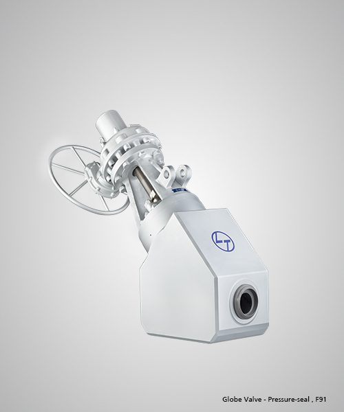
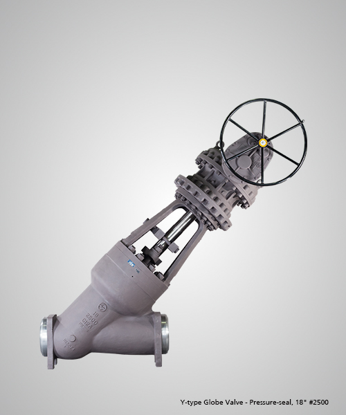
  • Special Features & Benefits Pressure-seal Globe Valve design conforms to ASME B 16.34. CE Marking – Meets requirements of Pressure Equipment Directive 2014/68/EU, Annexure III, Module H Atex - Meets requirements of Atex Directive 94/9/EC (ATEX), category 2 non-electrical equipment Safety Integrity Level for Automated Valves - SIL 3 certification available Pressure-seal Globe Valves (up to Class 2500) used in Oil & Gas industry tested to ISO 15848-1 Class BH Pressure-seal Globe Valves successfully tested to Shell Design Validation Test 77/300 and witnessed by Shell Inspectors Valves in intermediate classes reduce total cost of ownership Pressure-Seal mechanism utilizes line pressure to enhance seal; ensures sealing integrity at higher operating pressures. In-situ hardfaced seat design for all sizes Higher hardfacing thickness (3 mm) to ensure consistent hot hardness Body-guided Disc offered in Pressure-seal Globe Valves (all sizes/classes) provides disc stability and avoids vibration of the disc-disc nut assembly Disc guides hardfaced for longer life Customised deposition process in F91/ C12A valves to avoid delamination of hardfaced surfaces Live loading of bonnet bolts for F91/ C12A valves Special high purity graphite packing (seven rings) provided for pressure rating > Class 2500 in Power applications
    Details
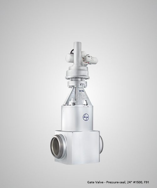
  • Special Features & Benefits Pressure-seal Gate Valve design conforms to ASME B 16.34. The design was successfully validated by conducting in-house High Pressure High Temperature (HPHT) Gas Tests on ultra-high pressure valve prototypes. Flow Interruption Test successfully conducted on 8" Class 600 Pressure-seal Gate Valve suitable for Main Stream Isolation Valve (MSIV) service in nuclear power plants - at Areva, Germany. Fugitive Emission - 14" Class 2500 Pressure-seal Gate Valve (test pressure of 431 bar at ambient and 289 bar at 400 degree C) has been tested successfully as per ISO 15848-1, endurance Class CO2 and Tightness Class BH CE Marking – Meets requirements of Pressure Equipment Directive 2014/68/EU, Annexure III, Module H Atex - Meets requirements of Atex Directive 94/9/EC (ATEX), category 2 non-electrical equipment SIL3 Safety Integrity Level for Automated Valves Pressure-seal Gate Valves (up to Class 2500) used in Oil & Gas industry tested to ISO 15848-1 Class BH Pressure-seal Gate Valves successfully tested to Shell Design Validation Test 77/300 and witnessed by Shell Inspectors Valves in intermediate classes reduce total cost of ownership Pressure-Seal mechanism utilizes line pressure to enhance seal; ensures sealing integrity at higher operating pressures. Higher hardfacing thickness (3 mm) to ensure consistent hot hardness Disc guides hardfaced for longer life Customised deposition process in F91/ C12A valves to avoid delamination of hardfaced surfaces Live loading of bonnet bolts for F91/ C12A valves Special high purity graphite packing (seven rings) provided for pressure rating > Class 2500 in Power applications Live loading of bonnet bolts and gland bolts for all valves in F91/ C12A construction  

    Details
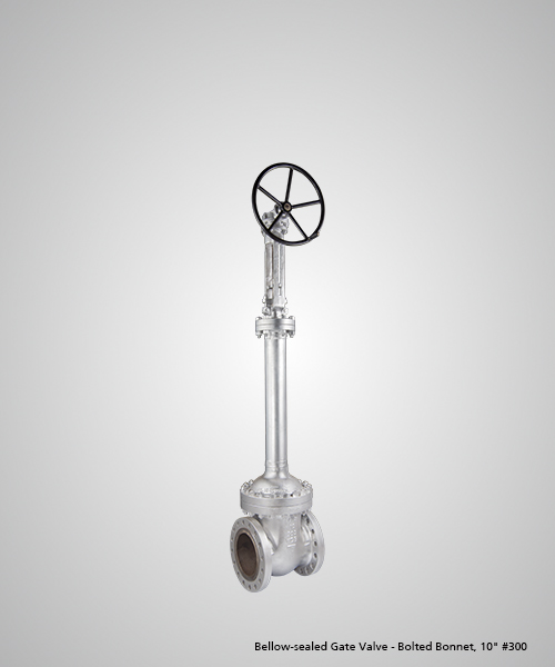
  • Special Features & Benefits Fugitive Emissions - Complies to ISO 15848-1: 2006 Class AH leakage SIL3 Safety Integrity Level for Automated Valves The bellows lifecycle is designed as per MSS SP-117 Metal bellows seal the moving stem and increase durability of packed stem seal valves Bellow provide a barrier between the stem at its point of entry through the pressure boundary and the process fluid within the valve, to eliminate stem leakage An anti-rotation device is provided in the bonnet to ensure bellow does not get twisted during assembly and disassembly or by vibration Bellow-sealed valves are usually leak tested using a mass spectrometer to detect leakage rates below 1x10E-06 std.cc/sec. Bellow-sealed bonnets are backed up with a standard stem packing set and a leakage monitoring port between the bellows and the packing in order to prevent catastrophic release of hazardous fluid in the event of a bellows leak.
    Details
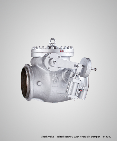
  • Check Valves
    • Pressure-Seal mechanism utilizes line pressure to enhance seal; ensures sealing integrity at higher operating pressures. Customised deposition process in F91/ C12A valves to avoid delamination of hardfaced surfaces Live loading of bonnet bolts for F91/ C12A valves
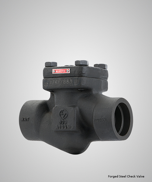
    Special Features & Benefits Check Valve design complies to BS 1868 and API 594 Offered with API monogram Fugitive Emissions - Complies with ISO 15848-1 (<50 ppm) Compliance to Annex III Module H of Pressure Equipment Directive 2014/68/EU Check valves successfully tested to Shell 77/300 and witnessed by Shell Inspectors Tilting disc and Axial Flow check valves can be also offered Internal hinge design, no hole in the body, eliminates leakage path Inconel overlay/ cladded option available
    Details
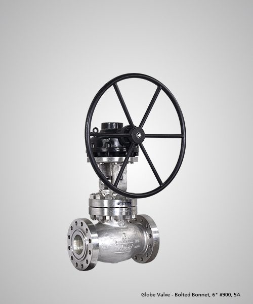
  • Globe Valves 
    • Pressure-Seal mechanism utilizes line pressure to enhance seal; ensures sealing integrity at higher operating pressures.
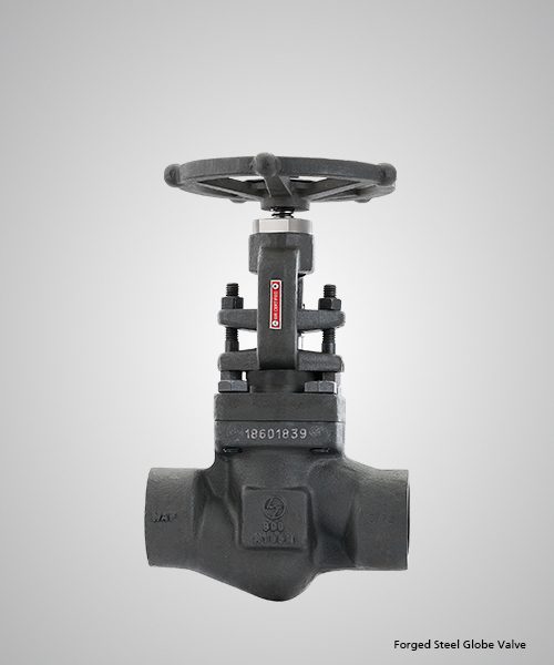
    • In-situ hardfaced seat design for all sizes
    • Higher hardfacing thickness (3 mm) to ensure consistent hot hardness
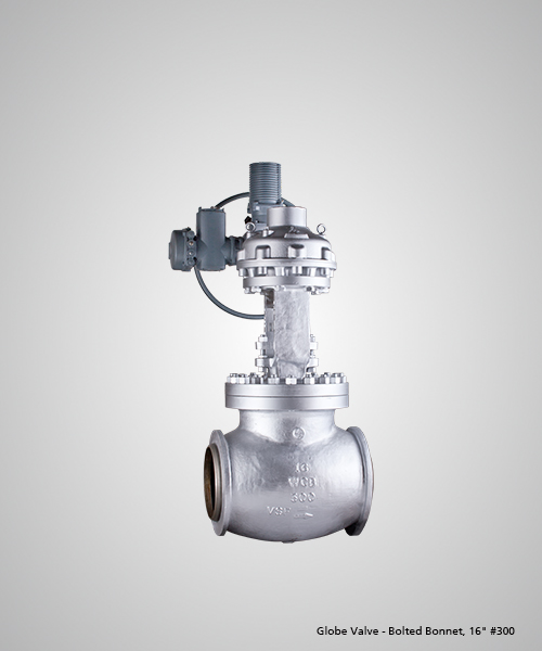
    • Body-guided Disc offered in all sizes/classes to provide disc stability and avoids vibration of the disc-disc nut assembly. Disc guides hardfaced for longer life
    Special Features & Benefits Check Valve design complies to BS 1868 and API 594 Offered with API monogram Fugitive Emissions - Complies with ISO 15848-1 (<50 ppm) Compliance to Annex III Module H of Pressure Equipment Directive 2014/68/EU Check valves successfully tested to Shell 77/300 and witnessed by Shell Inspectors Tilting disc and Axial Flow check valves can be also offered Internal hinge design, no hole in the body, eliminates leakage path Inconel overlay/ cladded option available  
    Details
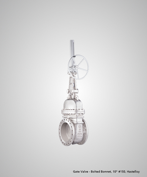
  • Special Features & Benefits Gate Valve design complies to API 600, Edition 13 Offered with API 600 monogram Fugitive Emissions - Complies to API 624 and ISO 15848-1 (<50 ppm / Class AH leakage levels, optional) Gate Valves tested to API 624 at Yarmouth Research Lab, Maine, USA Body gasket leakage <100 ppm observed on eight sizes tested as per API 624 Annexure A Fire Safe - By design and tested to API 607/ ISO 10497 CE Marking - Meets requirements of Pressure Equipment Directive 2014/68/EU, Annexure III, Module H PED Module B1 Design Examination Certificate (certified by DNV) available ATEX - Meets requirements of ATEX Directive 94/9/EC (ATEX), category 2 non-electrical equipment SIL 3 Safety Integrity Level certificatation is available Gate valves successfully tested to Shell Design Validation Test Procedure 77/300 and witnessed by Shell Inspectors Robust stem-wedge design connection successfully tested as per API RP 591 Annex B Hardfaced body guides and wedge slots (sizes >24”) Inconel overlay/ cladded options offered  
    Details
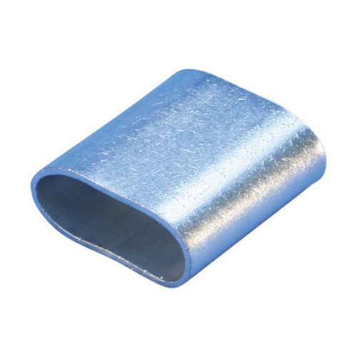
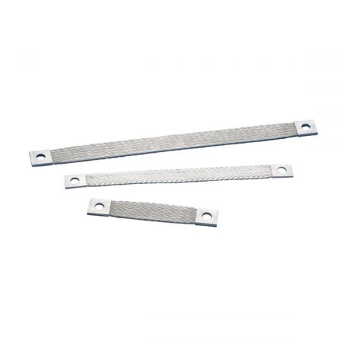
  • Features PB Lug for Flat Braids
    • Crimp to FTCB or FRCB braids to create custom flexible connections
    • Crimped and drilled using BD Crimp and Drill Tool or Crimping Tool for Hydraulic Work Center
    • RoHS compliant
    4.5 PB lug
    Details
  • Features CPI Grounding and Bonding Braid, Stainless Steel High-quality CPI stainless steel grounding and bonding braids can be installed in extremely corrosive environments, like offshore applications or coastal applications. The full range of CPI braids are ideal for applications using stainless steel pipe or tanks, like the food and beverage industry, building industry, transportation, oil and chemical industry. nVent ERIFLEX offers 316L stainless steel braids and lugs, one of the highest resistant stainless steel options on the market. Our proprietary manufacturing process has been optimized to provide the best braiding, crimping, cutting and punching
    • Superior abrasion, corrosion, chemical and UV resistance make CPI braids ideal for outdoor applications
    • Great for expansion joints where constant movement requires a flexible and durable solution
    • Ready to use out of the box, eliminates the need for cutting, stripping, crimping and punching
    • Quick and easy to install
    • Resistant to vibration and fatigue, reducing maintenance
    • Will not rust or discolor, so the appearance will never fade or change
    • Excellent electrical contact
    • No additional lugs or terminals needed
    • Non-magnetic material
    • Recommended by the EMC/EMI directives
    • Performs to the class C5 (very high) category as per ISO® 12944-2
    • EAC compliant
    • RoHS compliant
    4.4 CPI    
    Details

Title

Go to Top